Overview
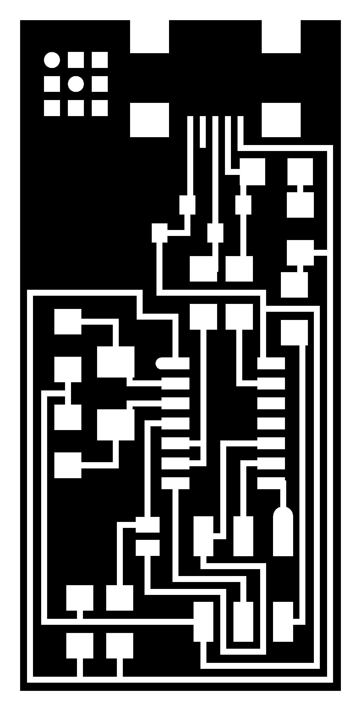
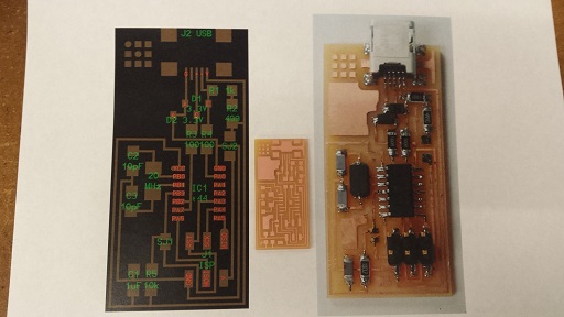
This week's main focus is for us to develop the skills and techniques involved in PCB (Printed Circuit Board) fabrication. We learned milling, soldering and programming the board, as well as how to make an IDC ISP cable, which we use to connect two headers. We were given a couple of different pre-designed PCBs to start with. In future weeks we will learn how to design our own circuit board and how to write our own programs. Here's the design I started working with:

Milling
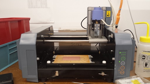
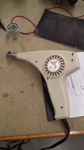
Here's a picture of the milling machine we used:
Rob has a detailed list of instructions on how to use a milling machine to print the circuit board. Here are some of the precautions that I wanted to add:
- After sticking the board to the milling machine using double-sided tape, be sure to press all corners of the board to make sure that it sits flat on the sacrificial layer.
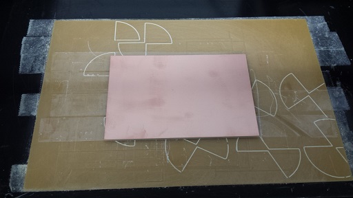
- When establishing the z-zero, it would be helpful to tap the endmill onto the board to make sure it touches the board firmly. Then hold down the endmill and tighten the setscrews. A piece of thin plastic could be used to test if there's no space left between the endmill and the board.
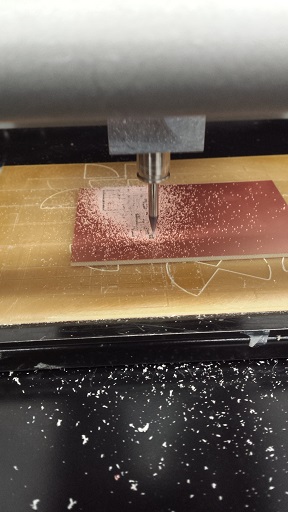
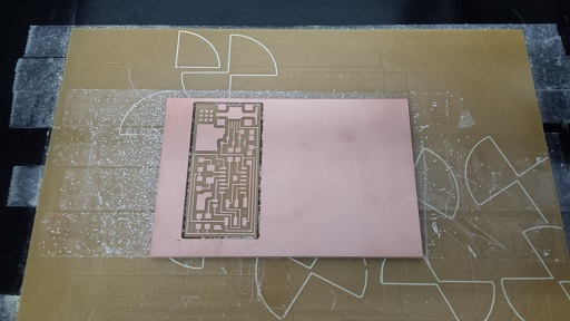
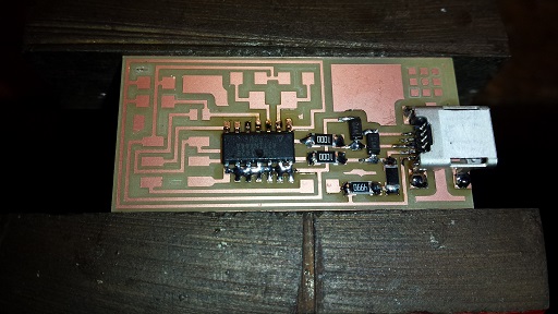
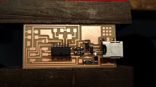
Here's a picture of the milling machine working in progress and the finished board:
Soldering
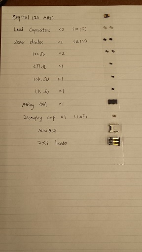
Soldering is definitely a skill that requires lots of practice. Before soldering, it is helpful to collect all the components and stick them onto a piece of paper with the correct labels; as some of the components look exactly the same:
Here are the main tools used for soldering:
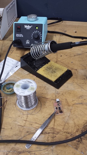
- Soldering iron melts the solder; we used temperatures between 650 and 700 degrees
- Tweezers are very helpful as the components are either too small or too hot to be held by hand
- Copper braids help remove excessive solder
- Hot air gun can also be used to remove a component from the board (use tweezer to hold the unwanted component, hold the board above the tabletop while blowing hot air near the component, until the solder melts and the board drops)
General Steps on Soldering:
- Clamp/tape the board somewhere and make sure that it does not move when it is worked on
- When the soldering iron is heated to desired temperature and the light starts flashing, melt some solder on the iron and rub the tip of the iron against the moist sponge pad to make the tip of the iron shiny and clean
- When soldering a resistor, heat up one of the copper pads on the board first, then melt a little bit of the solder to help hold the resistor in place. Then, on the other side of the resistor, heat up both the pad and the side of the resistor such that the solder can melt and connect the side of the resister and the copper pad
- There are two ways to solder a component with tiny "legs". One is to heat up both the pad and the leg that we want to solder together, hold the iron on the pad and place the solder wire on the tiny leg. When the leg is hot enough, the solder wire will melt and flow until it reaches the iron. For this week's mini USB, the legs are way too tiny; so we used the second method, which is to melt an excessive amount of solder across different legs first, then place the copper braid on top, use the iron to heat up the braid, and when the solder melts underneath, press down hard until the braid soaks up the solder and the liquid form of the solder appears on the surface of the braid. Then remove the iron and the braid together. (Otherwise the solder will solidify and the braid will be stuck to the tiny legs)
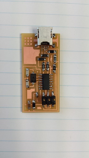
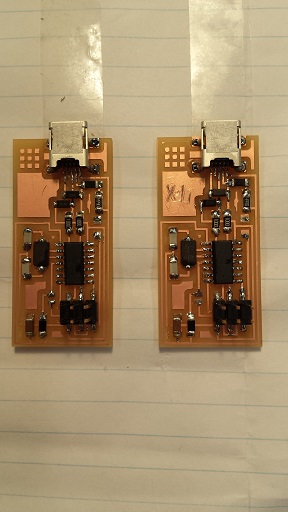
Here's a picture of the PCB that is ready to be programmed!
Programming the Board
I used Rob's Mac and followed his instructions to program the board:
- Connect the board to the laptop using the connection cable, making sure that no smoke is coming out anywhere. This is to make sure that there is no short circuits anywhere.
- Connect the board to the 6-colored cable (6-conductor ribbon cable) which is already connected to the computer.
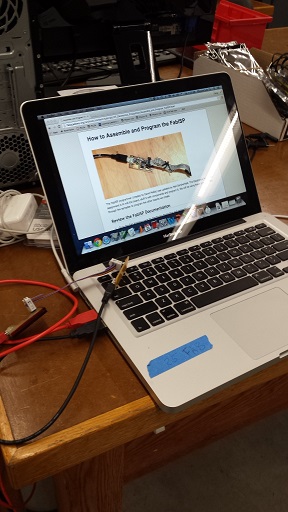
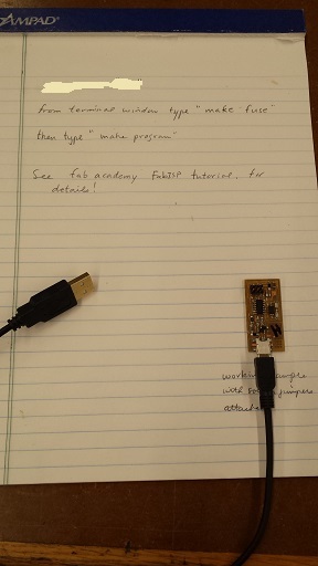
- Open the terminal on the laptop, make sure it goes to the right directory. The commands we have used for programming are "make fuse" and then "make program". This is also written on Rob's notes. In the end it should say ”program okay“ or something like that.
- Unplug the 6-colored cable, and unplug and replug the programmed board, the laptop should recognize it as a USB. To test that on a Mac, hold down "Option" key and click on the top left "Apple" icon. First option should be System Information. On the left-hand panel, click on "USB" and then on the top of the screen it should say "FabISP".
- Remove/desolder the jumpers (the 0-ohm resistor and the blob of solder) to make the programmer permanent.
I ended up creating two boards because the first one programmed okay but was not recognized as a USB when it was plugged into a computer. Rob and I could not figure out why, as all the components seemed to be well connected to the copper pad. Some of the people in the Harvard section tried desoldering and resoldering the mini USB and it worked; I may try that as well next time. Fortunately the second one worked well and it has my name on it! :)
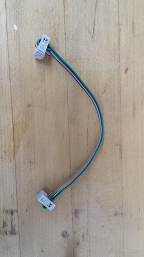
Making an IDC ISP Cable
Rob showed us a good example and a bad example when making a cable:
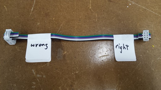
The process was fairly straightforward; I used a clamp tool to help tighten the IDC socket before putting on the cap on the outside:
I wanted to thank Rob for showing me how to mill, solder and make a cable, as well as for helping me program the board and try to figure out what was wrong with the first one. I also wanted to thank Dixon and Ben for showing me how to solder tiny legs.